

Bring magic to life with an automated, motion reactive shake-the-maze game! Using components from an Arduino starter kit
and common materials around the house, this is a customizable game to
let you feel like a wizard while learning the ways of servo motors and
light sensors.
In this game, wave your hands over the light sensors to control the speed and rotation of the motor and try to get all your marbles (or beads) into the cup. For a multi-player version, have each player choose a color or take turns playing and timing each other. Build interchangeable versions with different themes, multiple stories, add more sensors, etc.
This particular design was inspired and built by re-purposing materials found around the house. Look around for otherwise unused items or visit a local thrift store for quick and inexpensive ways to encase your project. Exercise your design skills and change the components of this project to fit your needs, wishes, and on-hand materials!
Here's a video of the game in action!In this game, wave your hands over the light sensors to control the speed and rotation of the motor and try to get all your marbles (or beads) into the cup. For a multi-player version, have each player choose a color or take turns playing and timing each other. Build interchangeable versions with different themes, multiple stories, add more sensors, etc.
This particular design was inspired and built by re-purposing materials found around the house. Look around for otherwise unused items or visit a local thrift store for quick and inexpensive ways to encase your project. Exercise your design skills and change the components of this project to fit your needs, wishes, and on-hand materials!
Materials

Electronics
All electronic materials used for this tutorial can be found in this Arduino starter kit.
- Arduino Uno
(or other Arduino board)
- Micro Servo Motor
+ Arms + Mounting screws (2)
- Two (2) Photoresistors
- Two (2) 10 kΩ Resistors
- Breadboard (mini)
(or PCB Board
)
- Breadboard wires (or 24 gauge stranded wire for PCB board)


- Clear round vase
- Small solar path light stand

- Cardboard box and cardboard sheet (for maze barriers)
- Plastic bag or saran wrap (maze cover)
- Beads (or other round objects that can fit through a drinking straw)
- Plastic cup
- Straws (two or more)
- Small, sturdy tuperware lid
- Four (4) popsicle sticks (or skewers -- to stabilize the base)
- Optional: Small toy truck
with movable bed or other mechanical lever
Tools
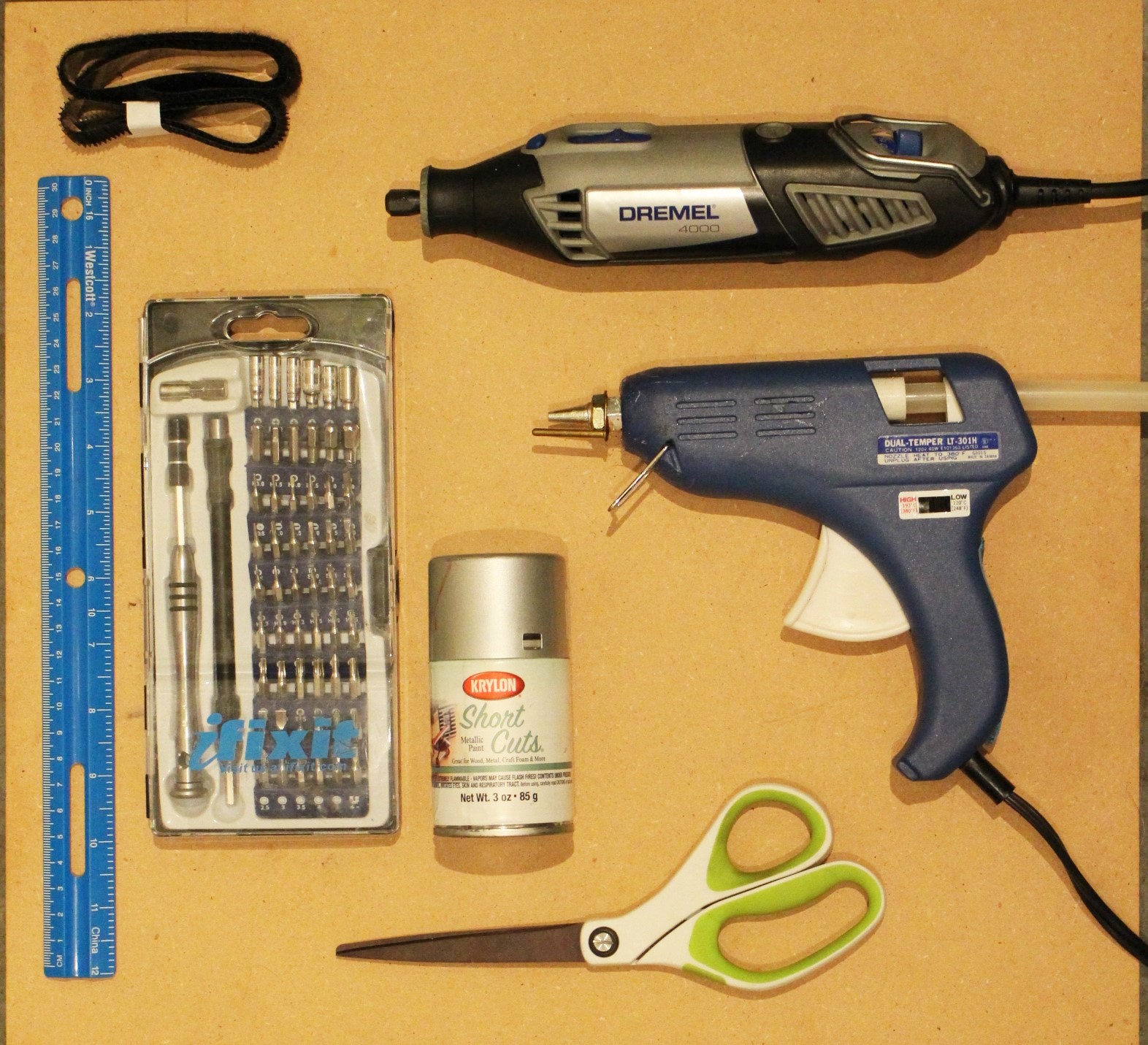
- Hot glue gun
- Dremel
(or a drill
)
- Scissors
- Screwdriver and/or Driver Kit
- Ruler
- Spray paint or other (permanent) paint
- Velcro strips
 .
.Build it! Pt. 1: Electronics!

Connect t-shaped motor arms to servo motor.
Connect servo motor positive lead (red wire) to Arduino 5V pin, servo negative lead (black wire) to Arduino GND (ground) pin, and the data pin (orange or yellow wire) to Arduino Digital Pin 9.
If adding a switch, use the switch to interrupt either the servo 5V supply or the data signal.
2. Connect first photoresistor to Arduino.
Connect one side of the photoresistor to Arduino 5V. Connect other photoresistor lead to Arduino Analog Pin A0, then to 10 kΩ resistor (in series). Connect other resistor lead to ground.
3. Connect second photoresistor to Arduino.
Same procedure as first photoresistor, but connect to Arduino Analog Pin A1.
4. Write program to read in analog value from photodiodes and use it to adjust the motor speed. Here's a sample program for you to use use and/or modify as you wish :)
In this program, lower light signals increase the rotational speed of the servo motor (aka as it gets darker the motor speed increases) and if there is a change in the light signal for both of the light sensors, the motor jolts.
Build it! Pt. 2: Maze!


1. Cut hole in top of cardboard box (maze container).
2. Design the maze!
Mark where you want the barriers to go, and decide how difficult or easy you want to make your maze (the one pictured was somewhat difficult).

Also be sure to allow one side of the box to open and reload the game.
 3. Measure width of box, cut out cardboard slats to fit width of box, and cut holes in slats for maze.
 4. Hot glue slats onto maze container.
5. Cut holes for straws at end of maze, attach straws with hot glue.
6. Paint maze container!

7. Cut plastic bag or Saran wrap and hot glue to top of maze.
Build it! Pt. 3: Maze Base!

 There are lots of different ways to build a base for the maze container! Peruse unused objects around the house and challenge yourself to think of, and try, at least three different approaches. Or you can use my design, but that's less fun :)
1. Cut out cardboard bottom for plastic cup, hot glue onto cup.
2. Attach maze to top of plastic cup with velcro strips.
3. Cut slots in plastic cup for drinking straws. Also may want to cut a "door" in the plastic cup to retrieve your marbles (..or beads).

4. Remove toy truck lever mechanism and hot glue to bottom of plastic cup. Adhere to tuperware lid via screw(s) or hot glue.
For a simpler version, hot glue the plastic cup directly onto the servo motor arms.
 5. Hot glue servo motor arms to bottom of tuperware lid.
6. Screw, or hot glue, popsicle sticks (or skewers) to servo motor mounting sides (the two sides of the servo motor base that stick out).
This helps stabilize the maze base and provides a more secure connection for the servo motor to the project base.

7. Paint!
Build it! Pt. 4: Motion Detector Case
 Going for a similar crystal-ball-esque look? Awesome! Use a clear, round vase. There are more more ways to house the photoresistors, let your imagination run wild! If you enclose them completely, use a sufficiently translucent object (dark greens and blues will reduce the signal).
1. Coat photodiode electrical connections in a thin layer of hot glue (or epoxy, for a super permanent connection).


2. Push sensors through stand until both are just barely sticking out the top.
If the sensors are getting stuck, try adding skewers or toothpicks to help push them through.
3. Orient the sensors in different directions at the top of the stand. In this version, one faces directly upwards and the other faces horizontally out towards the user.
Build it! Pt. 5: Project Base & Case

Let loose your creativity and ingenuity! In this design, a tuperware container holds (and hides) the electronics. Since I wanted an opaque, rectangular base, rather than using the tuperware lid, I took part of the case from a discarded printer/scanner and spray painted it copper.
 For the base, use a study material that can withstand the motor movement (avoid materials that flex). Good materials for the base include thick tuperware lids, wood, or metal. Consider available tools as well -- unless you have a drill (or other appropriate power tool), you'll want to use material that can be cut with hand tools.
2. Determine location for maze base and motion detector stand. Mark with pencil.
Consider that the maze base will rotate, so double check that it clears the motion detector stand within 360 degrees of rotation.

3. Measure size of servo motor and cut hole in base (for just the body of the servo motor, keep mounting arms on top of base). Push servo motor body (and wires) through hole, hot glue popsicle sticks to top of base.

4. Drill small hole in base for motion detector wires. Place motion detector stand on base, push wires through hole, and hot glue stand to base.

5. Glue switch onto base in an easily accessible location.
6. Adhere base to project case with velcro strips.
Finish, Test & Play!

2. Place Arduino and breadboard in project housing and test our your game!
The Arduino can also be powered with a 9V battery for a transportable game. When you're not using the game, unplug the 9V to avoid draining the battery super quick (or you can add a switch between the 9V battery plug and the Arduino).
3. Test the system by waving your hands over the motion detector and check that the motor changes speed.
4. Adjust any remaining aspects of your game.
5. Challenge your friends and family to play your personalized, motion controlled game!
Maybe even let them design their own maze level :)


