The following tutorial is a simple capacitive soil moisture sensor that uses a co-planar capacitor from the Zero Characters Left blog. The sensing circuit can be constructed for less than $25.00 w/ little or no prior experience in hardware or software prototyping. Experiment with and modify the system to create a version that suits your own needs!
Also, you can power this entire system using a portable solar USB charger.. :)
Materials

-- Raspberry Pi Microcontroller
- This tutorial is based on a fully set-up Raspberry Pi, including GPIO libraries + GPIO cable
w/ breadboard connector. I also recommend setting it up for wireless + SSH.
- Other microcontrollers, like an arduino
, also work.
- This resistance was the best for my system, but a different resistor value might work better for your own setup. Experiment w/ different value resistors and see what happens!
- Save the two EAGLE files (schematic and board file), then send to OSHPark. It costs ~ $10.00 for three, yay!
-- Breadboard, breadboard wires + GPIO breadboard adapter
- This is the bare minimum needed to built the system. I recommend that you use better/more permanent connections once you have tested the system and made sure that it all works as expected.
Tools

-- Soldering iron
- A soldering iron is (almost) essential for this project, especially for attaching wire leads to the co-planar capacitor.
-- Epoxy
-- Optional (but highly recommended): Multimeter (for testing and debugging!)
Operational Principles
1. Soil is made up of four main components: organic matter, sand, silt, and clay.
Between these are air gaps that can be filled with water. Here's a diagram of different soil water contents:
 |
| Source: tankonyvtar.hu |
2. Water conducts electricity better than air. This information allows for tons of different types of soil moisture sensors. This design uses a capacitive sensor: the capacitance of the sensor changes based on the amount of water in the soil.
Sensor & Circuit Design
An RC circuit provides a quick & simple way to measure changes in the sensor capacitance due to changes in soil water content.
A little bit of jargon: "RC" stands for Resistor - Capacitor. An RC circuit generates a time-varying current depending on the initial voltage, the initial current, and the circuit resistance and circuit capacitance. AKA: the output of the RC circuit depends on how much power you put into it and on the resistors and capacitors in the circuit.. which makes sense as that's all there is in the circuit!
 |
| Graph of RC circuit time constant. www.mindcreators.com |
Every RC circuit has an associated time constant, which is the time it takes the capacitor to reach ~ 63% of its maximum charge. The time constant equals the total circuit resistance times the circuit capacitance: τ = R * C The graph on the right shows how the voltage across the capacitor changes over time. The time constant is used to measure changes in the sensor capacitance. As the capacitance changes, so does the time constant. The equation above tells us that the time constant is directly proportional to capacitance, i.e. the time constant increases as the capacitance increases, and vice versa. In this system, the co-planar capacitor is the soil moisture sensor (or SMS). Theoretically, when the sensor is in air or dry soil, the time constant is small b/c the capacitance is low. In water or saturated/wet soil, the time constant is larger b/c the capacitance is higher.
Here's the circuit schematic:

If you want to boost or lower the signal, change the value of the resistor to increase/decrease the magnitude of the sensor output.
An Odd Observation: When the sensor was in dryish/damp soil and not registering, touching the resistor leads caused the sensor to output a reasonable signal. It also was sensitive to changes in light. These phenomena could be due to finicky connections & exposed wires; RC circuits tend to be sensitive to changes.
Build It!
Hardware:
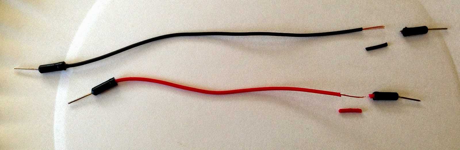
1. Solder wire leads onto the soil moisture sensor pads. Test connection w/ multimeter. If the sensor is electrically connected, coat in epoxy & let dry before continuing.
If you're using stranded wire + a breadboard, you'll need to find a way to connect the stranded wire to the breadboard (b/c trying to shove it into the breadboard holes will make you want to pull your hair out). I stripped two breadboard wires and soldered them to the sensor leads. My connections were stil a bit finicky. Try different methods and see what works best. Use available materials and keep it simple! 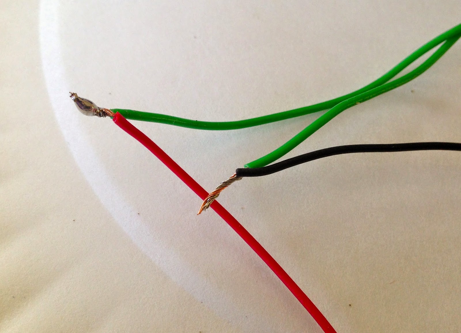
For the remaining hardware steps, reference the schematic and the picture below. 2. Connect the RPi GPIO pins to the breadboard. Connect the 3.3 V output pin to the "+" column along the side of the breadboard.
3. Connect the GPIO ground pin to the "-" column.
4. Connect one resistor end to the 3.3 V output (any of the holes in the "+" column). Connect the other end to any of the breadboard rows. Orientation of the resistor leads doesn't matter.
5. Connect GPIO pin 14 to the same breadboard row as the resistor. You can use a different GPIO pin, but remember to change it in the software program.
6. Connect one of the soil moisture sensor leads to the same breadboard row as the resistor + probe. Connect the other lead to ground (any of the holes along the "-" column). It doesn't matter which lead goes where.
Here's a photo of the breadboard setup (3.3 V connection is hidden by GPIO cable):

Software:
7. Write a code to measure the capacitance of the sensor! Use the fact that the time constant changes depending on the medium in which the sensor is installed (capacitance is much larger in water than in air).
Keep in mind that is a basic program and doesn't include a GUI. All commands are run on the Pi's terminal window (LXTerminal). The program prints the raw time constant, which is correlated to soil water content, a time stamp. If the reading is too low, the program also prints a reminder to water the plants. It also stores the raw data in a text file. To end the program, use "Ctrl + Z" or "Ctrl + C".
Modify and improve the program based on your own skills/needs. Remember to change the watering threshold based on your own experimental discoveries!
8. Test the code and determine your ideal threshold.
a) Test the sensor in water and air first; this provides the upper and lower bounds on the sensor output. If you find that the sensor is not reading in either of these mediums, change the value of the resistor until you get a reasonable signal. Be sure to record the reading for at least 5 - 10 minutes. It is helpful to plot the results in a program like Excel or R.
b) Place the sensor in a cup of dry soil. Add a small amount of water and measure changes in sensor output over time (wait at least 5 - 10 minutes).
c) If you are not getting a reading in either medium, try checking the electrical connections on the sensor.
9. Fix the program as necessary.
Your signal will likely be different than mine due to minor differences in your sensor and general setup. Use your findings from 8.a) & b) to find an approximate value at which your soil is too dry.
10. Run the program & use it to maintain consistent watering of your beloved plants! :D
Optional extension of the project: Making it survive outdoors!

Coat everything (except the sensor) in epoxy! .. Ok, so maybe not. Although, honestly it might work if you're careful. Otherwise, you'll want to scrap the breadboard for a PCB board + more 22-gauge wire. Molex connectors or something similar are a handy feature for the sensor.
Build process:
- Solder the resistor & the sensor leads to the PCB board.
- Your PCB may have copper lines connecting various pads; use this pattern on the PCB board to your advantage!
- If your PCB board does not have any pads connected, an easy way to connect components is to run wires along the bottom.
- Test the system w/ a multimeter or by running the code to be sure that it works as expected.
- NOW coat it all in epoxy!
- (Gently) shove the sensor circuit + RPI system into a waterproof container. My mom collects Talenti ice cream containers and they are super awesome for projects like this. Plus it's a great excuse to eat a container of ice cream :)

Wow these sensors look really interesting! At home I have some humidity sensors and I like them very much! Greetzs
ReplyDeleteThank you! I am blown away by the wide range of uses for capacitive sensors. Super cool, thanks for sharing your humidity sensors :D
ReplyDeleteThis comment has been removed by a blog administrator.
ReplyDeleteThe circuit schematic seems to be wrong, GPIO14 is connected to ground, instead to between the capacitor and the resistor... i don't think anything could be measured this way. Might even fry the controller if you set it to HIGH ;)
ReplyDeleteAh yes, been meaning to fix that. Thanks for reminding me, ha. Updated the schematic so it reflects the correct placement of the GPIO pin.
Deletehi jen, thanks for sharing your project! anw can i have the exact number of relative humidity by implementing this project?
ReplyDeleteGlad you found it useful! As-is, the sensor only measures volumetric water content, but you could definitely add in more sensors!
ReplyDeleteHi Jenny.....i was thinking....can we still use this method for water sprinklers without using the co-planar capacitors??
ReplyDeleteWhat i mean to say is, can we use this method for remotely accessed water sprinklers, but without the use of co-planar capacitors??
ReplyDeleteWhat i mean to say is, can we use this method for remotely accessed water sprinklers, but without the use of co-planar capacitors??
ReplyDeleteAbsolutely! Check out the irrigation controller tutorial: http://jenfoxbot.blogspot.com/2014/10/raspberry-pi-irrigation-controller.html
DeleteThanks Jenny...ill let you know if any thing else comes up..:) :)
ReplyDeleteVasthi Instruments are global leaders in manufacturing of dew point meter analyzer,gas analyzers, gas detectors,portable dew point meter, online dew point meter,dew point analyzer,particulate monitors, stack gas analyzers and have been supplying instruments to customers worldwide, Our multidisciplinary team of scientists, physicians, engineers, and regulatory consultants with decades of global experience brings you the quintessential mechanism that provides complete safety accuracy and durability. Vasthi Engineers was formed with visionary thinking and innovative ideas resulting in innovative products and solutions. We enhance our product quality by the continuous process of research and development. We have WIDE range of models to suite various site conditions and processes.
ReplyDeletehttps://www.vasthi.com/dew-point-meter/
Thank You For Sharing , Good Article
ReplyDeleteAlso do checkout Vasthi Instruments are global leaders in manufacturing of Dew Point Meter and have been supplying instruments to customers worldwide
Thank You For Sharing
ReplyDeleteDew Point Meter quality by the continuous process of research and development. We have WIDE range of models to suite various site conditions and processes.
thank you
ReplyDeletedew point meter
Thanks for having this article, it helps a lot. It’s a well-written blog and it is very informative. Keep on blogging, looking forward to see more of your posts!
ReplyDelete<a href="https://www.vasthi.com/dew-point-meter/"Dew point meter</a
Nice Information
ReplyDeleteVasthi Instruments are global leaders in manufacturing of Dew Point Meter ,gas analyzers, gas detectors,portable dew point meter, online dew point meter,dew point analyzer,particulate monitors, stack gas analyzers and have been supplying instruments to customers worldwide.
Focus on the consumer electronics charging products such as Power banks, Wireless Charge, Power Adaptors. We create products that help people realize the power of technology and make people’s lives better, easier and more fulfilling.
ReplyDelete