Friday, May 27, 2016

How to Use (and Choose) a Multimeter!


Checking your car battery life, debugging circuits, and finding that pesky short are all super useful functions that can be performed with just one awesome tool: the multimeter!

First of all, what the heck is a multimeter??   Excellent setup question! It's a handheld device with bunch of different electrical meters -- hence, multi-meter!

Measuring voltage, current, resistance, and continuity (aka electrical connection) are the most common uses of a multimeter.  Read on to learn what this means, how to do it yourself, and how to choose your very own multimeter!

Choosing a Multimeter!


There are a few key differences between multimeters, the main one being analog versus digital:
Analog multimeters show real-time changes in voltage and current, but can be difficult to read and log data.

Digital Multimeters are easier to read, but may take some time to stabilize.

There are also auto-ranging multimeters, that automatically detect the measurement range, and manual ranging multimeters where you have to choose a range yourself (or start with the highest setting and work down).


Other than those two main differences, you'll want a multimeter that has separate ports for current and voltage measurements (this is a safety issue, both for the meter and for yourself).

Next comes the fun part: features! Multimeters all have voltage and current meters (otherwise they'd just be called voltmeters and ammeters!), and most can also measure resistance. There are a variety of other "extra" features depending on manufacturer and cost (e.g. continuity, capacitance, frequency, etc.).


Second-to-lastly, there are a ton of different types of probe leads, including alligator clips, IC hooks, and test probes. Can't decide? Here's a kit that has four different types!

Lastly, always check the multimeter maximum voltage and current ratings to be sure that it can handle what you want to use it for.


Using a Multimeter!

But first! A quick overview of voltage, current and resistance!

My favorite analogy for electricity is the "water flowing through a pipe" analogy. In this analogy, voltage is similar to the water pressure, current is like the water flow (except with current you have electrons instead of water molecules!), and resistance is akin to the size of the pipe. Check out this tutorial for an awesome and thorough overview of electricity.

Keeping these analogies in mind helps us to figure out how, and what, we are measuring.


Measuring Voltage:


A voltage measurement tells us the electrical potential, or pressure, across a particular component.

Voltage is basically the "oomph" in our circuit, s so we want to avoid drawing any power from the circuit when we take a voltage measurement. This means we need to measure voltage in parallel with a particular component using infinite (or really, really high) resistance to prevent any electrical current from flowing into the meter.


Using a multimeter to measure voltage across a component (or battery!):


1. The black multimeter probe goes into the COM port, and the red probe into the port marked with a "V".

2. Switch the dial to the "voltage" setting (choose the highest setting if you have a manual ranging multimeter).

3. Place black probe on negative side of the component, and red probe on positive side (across, or in parallel with the component). If you get a negative reading, switch the leads (or just note the magnitude of the voltage reading).

Read the meter output and you're done! Not too bad :)


Measuring Current:


Taking a current measurement tells us the amount of electricity flowing through a given component or part of a circuit.

To measure current, we need to measure all of the flow in our circuit without consuming any power from the circuit and reducing the current measurement. This means we measure current in series with a component and we want our meter to have zero resistance.


Using a multimeter to measure current through a component:

1. The black multimeter probe goes into the COM port, and the red probe into the port marked with an "I" or an "A" (or "Amp").

2. Switch dial to the current setting (choose highest setting if you have a manual ranging multimeter).

3. Connect red probe to current source, and black probe to the input of the component, so that the current flows from the source, through the meter, to the component (in series with the component).

Read the meter output! If you're not getting a reading, switch to a lower setting.


Measuring Resistance: 


Measuring resistance is pretty straightforward, but you do have to disconnect individual components from a circuit to get their actual resistance, otherwise the rest of the components in the circuit can interfere with your measurement.

'


Using the multimeter to measure resistance of a component:

1. Put the black probe in COM port, and red probe in the port marked with a "Ω" or "Ohm" -- it should be the same port as the voltage port.

2.  Switch dial to setting marked with a "Ω" (may have to choose approximate range for manual ranging multimeter).

3. Place probes on either side of the component (orientation doesn't matter).

Read the meter output and you have conquered resistance!


Bonus: Measure Continuity!


The continuity measurement checks if two points in a circuit are electrically connected, otherwise known as a conductance test. Before measuring continuity, be sure that the circuit power is OFF.


Using the multimeter to measure continuity: 

 1. Place black probe in COM port, and red probe in voltage port.

2. Switch dial to setting marked with an audio symbol.

3. Place probes at points you want to check -- if the meter makes a beep sound, it means the two points are connected.

Le fin!


Go forth and measure all the things!


Now that we know how to use a multimeter, get crackin' on all those at home, DIY projects! To get you started, here are a few quick, practical, & fun projects:

1. Measure the resistance of your skin! Change the distance of the probe leads and see how resistance changes. Lick your fingers (or dip them in water) to see how moisture affects resistance!

2. Measure the voltage across AA, 9V, or other batteries around the house/workplace/school to locate dead, or dying, ones.

3. Make a ​lemon battery and measure the voltage and current output.

4. Use the continuity setting to check if different materials conduct electricity.

Monday, April 18, 2016

Interactive Survey Game


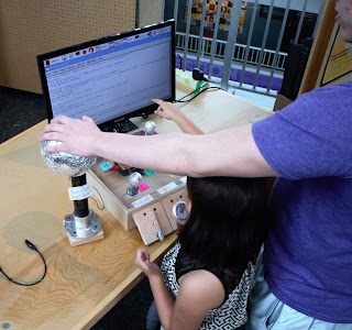
A survey questionnaire come to life! Use (nearly) any object to gather helpful data through an interactive, engaging, and fun multiple-choice survey.

This project uses the ​Makey Makey microcontroller in combination with a Raspberry Pi computer to read in participants' survey choices and save the results in a text file.


Planning & Design!

This general design is easily customized to fit a different theme. The only crucial design requirement is to use materials that conduct electricity for the survey pieces, or wrap non-conductive materials in aluminum foil.

Suggestions:
Prototype, prototype, prototype! Build different versions and test them on family, friends, co-workers, or (ideally) your target audience. Observe how folks interact with your survey, then use that to make it better! And always remember to keep it simple :)

Materials


- Makey Makey Kit
- Computer: Raspberry Pi

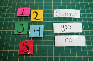
- One (1) ground piece, five (5) survey response pieces, one (1) submit piece, and two (2) yes/no pieces*

- 22 Gauge (stranded) Wire -- five (5) 10 - 16" strips and three (3) 6" pieces (ends stripped)

- Container:
-- Wood Box (12.5" x 12.5")
-- Plexliglass.("12 x 12")
-- Three (3) 2" x 2" wood panels

* Specific materials used in this design are detailed with the corresponding procedure, although customization is encouraged!


Tools

-- Safety goggles, woo!
-- Multimeter
-- Optional: Soldering iron, solder& desoldering wick
-- Ruler (or calipers)
-- Drill w/ both drill and driver bits
-- Flat wood file (to prevent splinters!)
-- Hot glue gun
-- Epoxy (permanent)
- Pliers

Reprogram the Makey Makey


To reprogram the Makey Makey, you'll need to have the Arduino IDE with Makey Makey drivers installed. Here's a thorough tutorial on how to do this.


1. Plug Makey Makey into computer and open the Arduino IDE.

2. Open (or copy) Makey Makey source code:
Here's the GitHub page for the Makey Makey.
Here's a direct link to download the full program. This is a .zip file, so be sure to extract all the files.

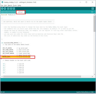
3. Reprogram the "click" key into an "enter" key.
For a thorough overview of how to do this, check out this tutorial.

4. Change the following keys:
These two keys are mapped in the survey program, but can be left as-is or you can choose to switch other keys (e.g. the arrow keys). Just be sure to change the mapping in the program.
A. Change the "g" into an "n".
B. Change "space" key into "y".


Build the Survey Response Pieces!


Specific materials used in this design:

- Two (2) wood blocks, two (2) golf balls, and one (1) jar lid.
- Aluminum foil
- Unistrut 1/2" Channel Nut with Spring
- Ten (10) 1/2" washers
- Plexiglass [or wood] (12" x 12")


Procedure:


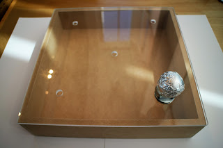
1. Wrap each of the survey response pieces at least 2 - 3 times with foil, hot gluing each layer.


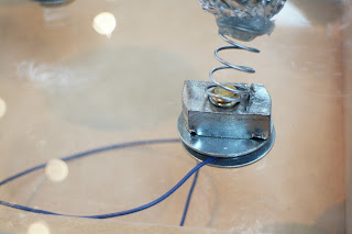
2. For unistrut spring pieces, hot glue (or epoxy) the top of the spring to the bottom of each survey response piece -- be sure that the metal of the spring is touching the foil of the survey piece.


3. Attach the survey pieces to plexiglass.

Determine location of survey response pieces and mark with tape. Drill a hole at each point.

Place a washer on either side of the hold and screw bolt into unistrut spring about 3 turns.


4. Connect a wire to each of the unistrut spring pieces.

Wrap wire around base of bolt (between washer and plexiglass). Hand tighten the bolt to secure wire without squishing it


Build the Ground Piece!


Specific materials used in this design:
- Styrofoam ball
- Metal pipe
- Flange stand for pipe
- Aluminum foil
- Twelve (12) washers
- 4 wood screws
- Wood panel (2" x 2")


Procedure

1. Build a stand for the styrofoam ball -- use conductive materials or wrap pieces in foil.


2. Wrap styrofoam ball in aluminum foil, leaving a "tail" of foil. Place ball on stand and push the foil tail against the inside of  Hot glue pieces together.


3. Cover the exposed end of the ground wire (24") to the inside, or bottom, of base and adhere with tape or epoxy.


5. Add a layer of two (2) washers under base to avoid squishing the wire, then connect base to wood pane via screws or epoxy.


Build the Enter Key!


Specific materials used in this design:

- Clothespin
- Wood panel (2" x 2")
- One (1) wood screw + one (1) washer
The screw should be about 1/4" longer than the wood thickness.
- Aluminum foil


Procedure:


1. Wrap one of the handles of the clothespin in foil.

2. Remove clothespin spring clamp, align other side of the clothespin on wood panel, and drill in a screw and washer.

Foil on the other side of the clothespin should make contact with the washer + screw when closed.

3. Reconnect spring clamp and other side (may need pliers). Epoxy bottom of clothespin to wood panel.


4. Use alligator clip or wrap wire around screw and secure with hot glue.


Make the Yes and No Keys! 

Specific materials used in this design:
- Two (2) plastic container lids
- Two (2) wood panels (2" x 2")
- Two (2) wood screws and washers
Each screw should be about 1/4" longer than the wood thickness.
- Aluminum foil


Procedure

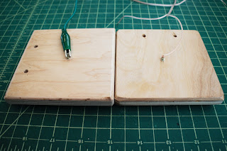
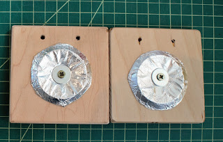
1. Cut circle out of container lids. Wrap in foil.

2. Align lids on wood panels and drill in a wood screw with washer on top -- be sure the screw slightly pokes through the back of the wood panel.


3. Use alligator clip or wrap wire around screw and secure with hot glue. 


Connect Pieces to Makey Makey


1. Connect ground piece lead to Makey Makey ground pads.

2. Connect survey game pieces to the first five (5) Makey Makey back header pins on the left: "w", "a", "s", "f", and "d".

3. Connect the no button to the last (6th) back header pin, "g"

4. Connect the yes button to the "space" pads.

5. Connect the submit piece to the "click" pads.


Load the Survey Program!

Using a Raspberry Pi computer means that all of the electronics can fit into the game box! Write up a program in Python to cycle through a series of survey questions and five possible choices that map to the survey response pieces.

Here's my code:
GitHub page!
Python program only.


Final Touches & Case!

This case is designed to withstand high traffic, experimentation, and children -- and to be easily (and cheaply) fixable and adjustable. Use this design or customize your own!

Materials:
12.5" x 12.5" wood box
1" x 10 " wood panel


Procedure:
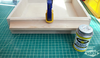
1. Epoxy wood panel onto front of box.

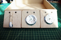
2. Drill the submit, yes, and no keys into the wood panel.


Recommended to put the "submit" button on the far right (switched this after further testing and feedback).


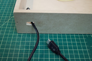
3. Drill hole large enough to fit an HDMI port in the back panel of the box.

I used two 3/8" bits and filed down the hole until the HDMI port fit.


 4. Label the survey game pieces and the submit, yes, and no keys.


Test, & Install!

Connect the Raspberry Pi to a monitor, keyboard, and the Makey Makey. Test the program and double check all the keys. Once everything is up and running, remove the keyboard (and mouse if connected). 

Load the python program, stand back, and let passersby have a blast participating in a survey!

Creative Commons License
This work by Jennifer Fox is licensed under a Creative Commons Attribution-NonCommercial-ShareAlike 4.0 International License