Monday, November 9, 2015

EL Wire Light Up Dog Harness

Whether it’s to keep Fido (or in my case, Marley) visible on an adventure or as an awesome all-year-round costume, a light up dog harness is an excellent accessory for your favorite pup.

 
 EL wire is a great option for wearable lights. It stays cool, is flexible, and comes in lots of different colors. This design uses the SparkFun EL Sequencer to automatically turn on EL wire when it is sufficiently dark outside so you don't have to worry
about locating Mr. Dog to turn the system on.

Here's a video tutorial for this project.


Recommended Reading

If you are new to electronics, EL wire, or the EL Sequencer, or would like more information on the main components in this project, check out this tutorial.

As this design also uses a lithium ion battery, I also recommend reading this tutorial to give you an overview on proper care and handling of lithium batteries.


Materials

Electronics

  • EL Wire
    • EL wire comes in variety of colors, pick your favorite!

Harness Materials

  • Dog harness
    • A vest or backpack will also work.
  • Waterproof jacket with pocket(s)
  • Optional: Tupperware or other sealable plastic container


Tools

  • Safety goggles
  • Soldering Iron
  • Wire Cutter/Stripper
  • Epoxy (waterproof)
  • Scissors
  • Needle + thread OR fabric adhesive
  • Optional: Velcro


Build it! Pt. 1

**CAUTION:** Although it is low current, EL wire runs on high voltage AC (100 VAC). There are exposed connections on the EL Sequencer board so BE CAREFUL when handling the board. Always double (and triple) check that the power switch is OFF before touching any part of the board. For final projects, it is recommended to coat all exposed connections in epoxy, hot glue, electrical tape, or other insulating material.


1. Test the EL Sequencer with EL wire.
Connect EL Wire, inverter, and battery to EL sequencer.
Turn on power switch and check that the EL wire turns on (should be blinking). You can connect, and control, up to 8 different strands of EL wire.

2. Solder header pins onto 5V FTDI pinholes on the EL Sequencer.
3. Solder header pins to the "GND," "VCC," and "A2" pinholes EL Sequencer (right side).


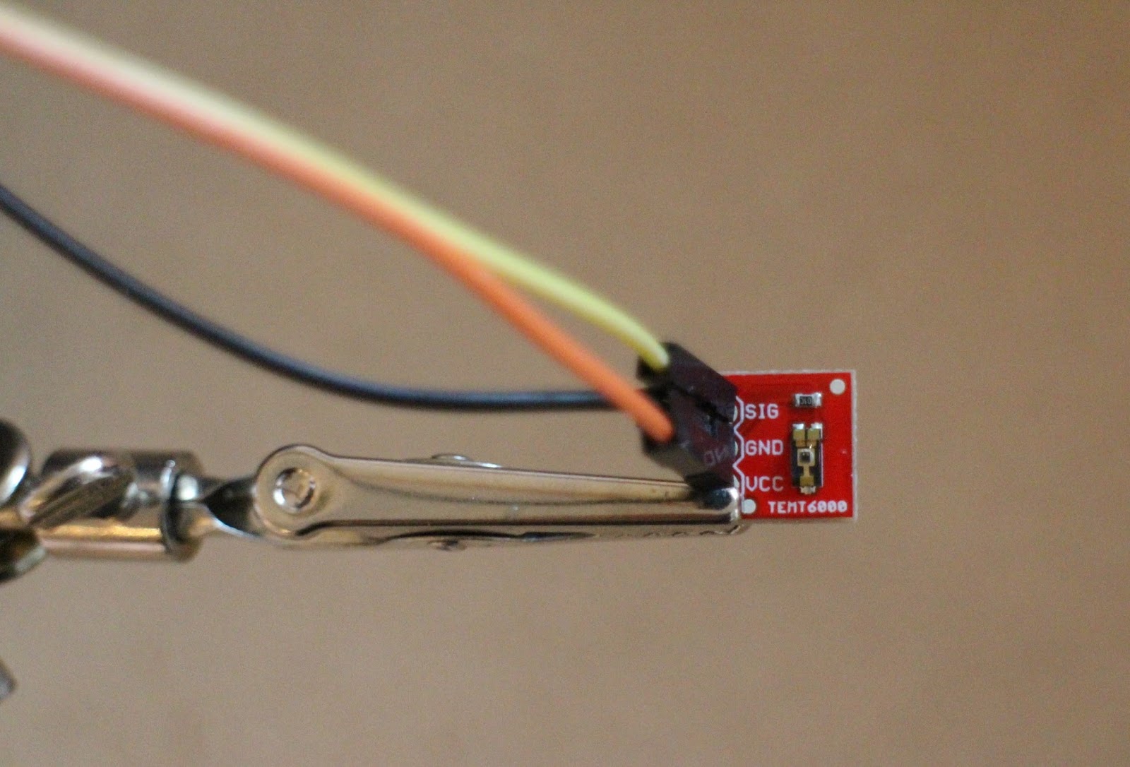
4. Solder male end of breadboard wires to ambient light sensor. Coat exposed metal on the sensor in epoxy (do not coat actual sensor).
Note: Recommended to solder the pins on the bottom of the sensor so that the sensor can more easily be attached to the harness (found this out the hard way..).


Build it! Pt. 2 


1. Attach EL Wire to harness.
Sew EL wire onto harness with dental floss for a strong, durable bond. Can also use an appropriate fabric adhesive.

For straps/buckles: leave about 1" of unattached EL wire on either side of the strap/buckle.


You can either wrap the ELwire for its entire length, or cut it and insulate the ends.


2. Make a durable pouch for the electronics.
For a waterproof pouch, cut out a pocket in a waterproof jacket. I also included a small tupperware container to house the electronics in the pouch to further insulate and protect them from weather and dog conditions.


Build it! Pt. 3

1. Attach electronics pouch to harness.
Sew pouch onto top side of harness, or wherever is comfortable and practical for your pup. Recommended to put harness on dog to find a suitable location for the pouch.


2. Cut small holes on underside of pouch for the EL wire JST connector and the light sensor wires.


3. Attach and secure light sensor to harness. Recommended to put harness on your dog and mark location for light sensor so that it faces upward.
There was an ideal flap in the rainjacket pocket for me to cut a hole, push the sensor through, and epoxy the other side. You can also use velcro or sew the light sensor onto the pocket or harness, just be sure that it stays stationary and won't get covered when the dog is moving.


4. If using tupperware, cut or drill holes in tupperware for EL wire JST connector and light sensor wires.
If you are not using tuperware, it is recommended to cushion the electronics and/or epoxy all connections (except the JST connectors) to protect them from your dog's antics.


5. Connect EL wire and light sensor to EL Sequencer (through holes in the tuperware), then epoxy the holes to keep wires in place and maintain a waterproof seal.


Program It!

1. Connect EL Sequencer to computer via 5V FTDI BOB or cable. 

2. Program the EL Sequencer using the Arduino platform; the EL Sequencer runs an ATmega 328p at 8 MHz and 3.3V. 


3. Write a program to read in the analog value of the ambient light sensor, turn on the appropriate EL wire channels at a value that corresponds to low light, and turn off once the light sensor value is above the low light threshold.

Here's a sample program with a preset light threshold:
// EL Wire Dog Harness Program
// Turn EL wire on when ambient light is low.
// JenFoxBot
// Based on test sketch by Mike Grusin, SparkFun Electronics
void setup() {
  Serial.begin(9600);  
  // The EL channels are on pins 2 through 9
  // Initialize the pins as outputs
  pinMode(2, OUTPUT);  // channel A  
  pinMode(3, OUTPUT);  // channel B   
  pinMode(4, OUTPUT);  // channel C
  pinMode(5, OUTPUT);  // channel D    
  pinMode(6, OUTPUT);  // channel E
  pinMode(7, OUTPUT);  // channel F
  pinMode(8, OUTPUT);  // channel G
  pinMode(9, OUTPUT);  // channel H
  // We also have two status LEDs, pin 10 on the EL Sequencer, 
  // and pin 13 on the Arduino itself
  pinMode(10, OUTPUT);     
  pinMode(13, OUTPUT); 
  pinMode(A2, INPUT);  
}
void loop() 
{
  int x,status;
  
  //If ambient lighting is too low, turn on EL wire
  if(analogRead(A2) < 50){
    digitalWrite(2, HIGH); //turn EL channel on
    delay(1000); //wait 1 second
    
    //Keep EL wire on until light sensor reading is greater than 50
    if(analogRead(A2) > 50){
      digitalWrite(2, LOW); //turn EL channel off
      delay(10);
    }
    
    Serial.println(analogRead(A2)); // Use this to check value of ambient light 
    
    digitalWrite(10, status);   // blink both status LEDs
    digitalWrite(13, status);
  }
}
 
4. Check that the EL wire turns on when the ambient light is low, and turns off in bright light. 

Test it and Put it to Work!

Place EL Sequencer, inverter, and battery inside the pouch (and tupperware). Connect all components to the EL Sequencer and turn it on using battery power. Test it in low and bright light to ensure that it functions properly.

If system works as expected, put on dog and go exploring!

As an added bonus, you can use the electronics pouch to store other small, non-magnetic items. Enjoy!


Monday, September 28, 2015

Simple Leaf Blower Hovercraft

***

What better way to finish off the summer than a relaxing hover to the park?
This is an overview of a simple, inexpensive design that can be built for less than $10 if you are resourceful (and already have a leaf blower). Maximum cost, excluding the leaf blower, is about $50.
Here's a video of the hovercraft in action!
Recommended to use a gas powered leaf blower if you want to travel somewhere beyond your garage or workshop.
--------

Step 1: Materials


-- Circular piece of wood for hovercraft body w/ ~ 2 ft. diameter
Minimum area of ~ 10 sq. ft. (1 sq. meter).
-- Small circular piece of wood for anchor w/ ~ 6 in. diameter
-- Tarp
-- Cardboard
-- Optional: Propulsion mechanism (fan or PVC piping)

----------

Step 2: Tools


-- Leaf blower w/ output ~ 200 MPH*
A gas-powered leaf blower works best for this project and lets you travel anywhere, but any leaf blower will work as long as the output is powerful enough.
-- Staple gun*
-- Jigsaw* + safety equipment
-- Power Drill
-- Scissors and/or Blade Knife
-- Duct Tape
-- Sandpaper*
-- Screws* (~4)
*Not pictured

---------

Step 3: Procure Base


The area of the base of the hovercraft should be at least 1 square meter (10.8 sq. feet). This will support about 220 lbs of weight.
Wood is the best material for the base. There are lots of ways to source wood cheaply or for free. Mine was found discarded in an alley. You can also purchase plywood and cut it to a different shape.
Once you have the base, measure the diameter of your leaf blower nozzle, then cut a small hole in the base about 6 in. from the edge. Thoroughly sand all edges, including the hole.
Also sand the edges of the wood anchor.

---------

Step 4: Build it! Pt. 1


1. Lay base on top of tarp. Cut tarp around the base leaving at least 3 in. of excess tarp.
2. Loosely fold tarp over top of base; there should be room for the tarp to inflate about 1 in.
3. Use overlapping layers of duct tape to adhere the tarp to the top of the base.

----

Step 5: Build it! Pt. 2


1. Cut out 1 in. x 2 in. cardboard rectangles to go around the perimeter of the base.
Rectangle size is approximate.
As for the number of rectangles, you can be extremely precise and measure the base perimeter to calculate how many rectangles to cut, or you can be approximate and cut more as you need them (my preferred method).
2. Staple the cardboard rectangles to the base so that the sides and/or corners are touching.
3. Flip the base over, and add overlapping layers of duct tape across the middle of the base.
4. Find the center point of the base and mark it.
----

Step 6: Build it! Pt. 3


1. Find the center point of the wood anchor, and match it up with the center point of the base (on the bottom over the duct tape).
2. Drill the anchor securely into the wood base.
3. Cut about 10-15 ventilation holes around the anchor and on top of the duct tape. Area of each hole should be ~ 1 sq. in.
Suggested to start with a small number of holes (~5-8) then test w/ the leaf blower to see how it floats. It should be stable and not tip to one side. If it is tipping, cut more holes on opposite side of which it is tilting.
4. Flip over the base (so that the top is up) and adhere the leaf blower nozzle to the hole w/ duct tape.
------

Step 7: Test it and Take it to Town!


Power up your leaf blower and take it for a spin! Or a straight line.
You can also turn this into a rudimentary vehicle by adding a propulsion system. One easy way is to add a fan. Another is to use PVC piping to redirect some of the leaf blower airflow behind you. I'm considering testing the PVC method.. if there is interest I will post an addendum showing how to do this.
Many thanks to this YouTube tutorial for the general overview.

Wednesday, July 22, 2015

Motion Triggered Music Player


Turn on music as soon as you walk into a room! This tutorial covers a minimalistic entrance sensor that triggers music of your choice. The design can easily be adapted to suit a variety of needs (e.g. alarm system, motion-triggered lights, etc.).

The system is controlled by a Raspberry Pi, and aside from the RPi and speakers, the materials cost is extremely low (~ $20). Build time is approximately 1 - 2 hours.

For an inexpensive set of speakers, check thrift stores and/or friends' garages.

Materials


1. Raspberry Pi + Accessories
This tutorial assumes that the RPi has been set up and includes all necessary accessories (e.g. power cord, SD card, etc.). It is also recommended to use an RPi that has been set up for wireless and with a GPIO breakout cable.
Here's a tutorial on how to set up the RPi.

2. Infrared (IR) Breakbeam Sensor(s)

3. 10 kOhm Resistor

4. Speakers w/ 1/8" audio jack (standard headphone jack)

5. 22 or 24 gauge wire (min. 15 feet)
Recommended to get at least two to three colors (e.g. red, black & yellow).

6. Optional: PCB board and/or Connectors
Although not necessary, a small PCB is recommended to make the system more robust and longer lasting.
Add connectors between the sensor and RPi GPIO for simpler installation, transportation and to more easily allow for future customization.

7. Recommended: LED + 10kOhm Resistor (for testing)


Tools


1. Soldering Iron*, Solder & Solder Wick

2. Wire Strippers

3. Epoxy

4. Multimeter

5. Recommended: Breadboard + Breadboard Wires (for setup and testing)
*Note: If you do not have access to a soldering iron, you can twist wires together and coat in hot glue.

Step 1: Setup Raspberry Pi to Play Music


This project provides an overview for how to play a music file saved on the RPi SD card. Possible modifications include setting up the RPi to play music from an external USB drive or streaming music from a website.
1. Install updates w/ this command:
sudo apt-get update
2. Download example music file for testing:
wget   http://goo.gl/MOXGX3   -O example.mp3 --no-check-certificates
Note: This saves the file in whatever directory you are currently in.

3. Open the Terminal window and go into the folder with the music file
Use following command (switch “FolderName” for location of music file):
Cd /home/pi/FolderName
4. Type following command to play file over the audio output:
omxplayer example.mp3

Step 2: Build it! Pt. 1


Recommended to build the circuit on a breadboard and test prior to soldering any of the components onto the PCB board.

 
1. Extend the wire leads of the IR beam (2 wires: red & black) and IR receiver (3 wires: red, black & yellow).
Plan out and measure the route of the wires from where the IR beam and receiver will be installed to the speaker system. At a minimum, make each wire lead 3 - 5 ft.
Recommended to add connectors to the IR beam and/or receiver to make it easier to disconnect them and, if necessary in the future, modify the system.


If the schematic makes sense, skip the rest of the Build it! steps.

2. Connect the positive side of the IR sensor beam to Raspberry Pi 5V pin.

3. Connect the negative side of the IR beam to RPi ground pin.


4. Connect the positive side of the IR receiver to RPi 5V pin.

5. Connect the negative side of the IR received to the RPi ground pin. 


Step 3: Build it! Pt. 2


1. Connect the data pin (yellow wire) of the IR receiver to RPi GPIO pin 23.
 
2. Connect the 10kOhm resistor between the data pin/RPi GPIO pin 23 and the RPi 5V pin.


3. Recommended: Connect an LED + resistor across the IR receiver data pin (yellow wire).
Connect the positive LED leg to the IR receiver data pin. Connect the negative LED leg to the resistor. Connect the other side of the resistor to ground.


4. Plug in RPi and log in; check that IR beam turns on.
If you've connected the LED, it should turn on when the IR receiver gets the signal from the IR beam. Check that the LED turns off if you interrupt the beam.


Step 4: Code it! Pt. 1

The following is a basic program to play a song when the IR beam signal is broken (AKA when you walk between the IR beam and IR receiver). Here's the GitHub page.

Save the song of your choice to an easy-to-remember-and-type folder, in this example I used "FolderName" to designate the title of the folder in which the mp3 is saved.

Note: This program prints a message to the screen each time the song is played. This worked for my needs, as I wanted to have a log of each time music is played, but of course this code is just an outline of what is possible. Modify it to suit your needs :)
import time
from threading import Thread

import RPi.GPIO as GPIO
import subprocess


class AutoTrigger():
    def call_omxplayer(self):
        print ("playing " + self.file_path)
        pid = subprocess.call(['omxplayer', self.file_path], stderr=subprocess.PIPE, stdout=subprocess.PIPE)
        self.is_running = False

    def play_song(self):
        if not self.is_running:
            self.song_thread = Thread(target=self.call_
omxplayer, args=())


            self.song_thread.start()
            self.is_running = True

    def __init__(self, pin, file_path):
        self.pin = pin
        self.file_path = file_path
        self.is_running = False
        GPIO.setup(pin, GPIO.IN)
        '''
            This is a hack (the callback) thanks for python closures!
        '''
        GPIO.add_event_detect(self.
pin, GPIO.FALLING, callback=lambda x: self.play_song(), bouncetime=10)

   
def main():
    GPIO.setmode(GPIO.BCM)
    AutoTrigger(25, '/home/pi/FolderName/SongName.
wav')
    AutoTrigger(24, '/home/pi/FolderName/SongName2.mp3
')

    print ("Ready: !")
    try:
        while True:
            pass
    except KeyboardInterrupt:
        GPIO.cleanup()       


if __name__ == '__main__':
    main()

Step 5: Install it!


1. Check system for functionality. If system works as expected, coat all exposed electrical connections (except for RPi plugs) in hot glue or epoxy.
Be aware that epoxy is essentially permanent; use hot glue if you want to modify the system in the future.


2. Attach the IR beam to one side of your front door frame, and the IR receiver on the other side of the door frame, directly in line with the beam. Run the wires up and over the door frame.
It is somewhat tricky to align the IR beam and receiver; highly recommended to use the LED + resistor to quickly see when the beam and receiver are aligned. Use sticky tack or tape to help w/ alignment.
Secure the IR sensor via thumbtacks, nails, screws, etc. Suggested to run the wires up and over the door frame (instead of on the floor).

3. Place the RPi in a convenient and out-of-the-way location.
Consider where you want to place the speakers. If you need longer wires, measure the needed distance and solder in additional wires to the RPi power, ground and GPIO pins.


4. Set up the speakers.

5. Test!
Plug in the RPi and trigger the system to be sure that the music plays when you walk through the IR beam.

Step 6: Activate and Enjoy!


The only issue w/ this design is that the IR receiver range is shorter than I originally wanted, only about 2 feet. Some solutions to this problem would be to use a lens to magnify the IR beam or increase the power input.

Possible modifications of the project include using WiFi to stream music or podcasts, triggering lights, and/or using it to detect motion in and out of your home for a basic security system.. or to see how many times your cat leaves the house while you're gone.

Thanks for reading! Please check out and subscribe to my YouTube channel for more projects and other cool science stuff.

Happy building!

Sunday, May 24, 2015

DIY Money Blower Machine


A fun & whimsical way to collect donations for a variety of causes. Depending on the materials you have lying around your house, this machine can be built for free! Even if you have to buy all the materials, maximum cost is less than $15.
This is a minimalistic and easy design for makers of all experience levels! The whole machine takes about an hour to build.
------
Materials

1. Cardboard Box (not pictured)
Medium to small, somewhere around 12 in. x 12 in. x 12 in.
2. DC Computer/Electronics Fan
Recommended to harvest one from broken electronics equipment. Otherwise, these can be purchased online from a variety of manufacturers for ~ $5. Here's one website.
3. Power adapter cord (120 VAC to ~ 12VDC)
Recommended to repurpose an unused power cord lying around; old charging cords (e.g. phones, cameras, etc.) are perfect.
4. Saran Wrap
------
Tools

1. Wire strippers
2. Scissors
3. Soldering Iron*
4. Hot glue gun
5. Duct Tape (or other heavy duty tape)
*If soldering iron isn't available, tightly twist wires together and coat in hot glue.
------
Build it! Pt. 1


Optional: Spray paint, or paint, cardboard box.
1. Cut a 3 in. x 1 in. slot in the top of the cardboard box.
2. Cut windows into the 3 of the sides of the cardboard box.
Be sure to leave at least 1 - 2 in. of cardboard along the edges of each side.
3. Cut the remaining side into a door.
Cut along 3 of the edges (bottom, one side, and top) so that this side opens and closes, with one of the edges as the hinge.
4. Tape saran wrap on the inside of the cardboard box to cover the window holes.
Tape saran wrap onto the farthest most edge. Pull one side of the saran wrap tight and tape to box. Repeat with remaining sides. If there are loose areas, gently pull up tape and re-adhere to box.
------
Build it! Pt. 2


1. Cut connector ends off of the computer fan and the power adapter and strip wires.
For the computer fan, strip the red and black wires.
For the power adapter, separate the two wires and strip.
2. Connect the red computer fan wire to one lead of the power strip, and the black computer fan wire to the other power strip lead. Check that the fan turns on when the power adapter is plugged in.
3. If fan turns on, unplug the power adapter and solder the connections together. Coat in hot glue.
------
Build it! Pt. 3


1. Glue computer fan on the inside of the cardboard box, in the center of the side with the door.
2. Cut a hole in the center of the cardboard box door to expose the computer fan.
3. Cut a top vent in the cardboard box door.
Recommended to cut small slits, or cover larger vents with skewers or toothpicks.
4. Adhere the cardboard box door to the side.
I found strips of velcro lying around. Other ways to adhere are rubber bands, string, or just hot glue the sides together.
------
Test & Impress!

Add a few dollar bills to check that there is good airflow. If it works as expected, use at parties as a fun way to collect money for food + drink, or incorporate into your next fundraiser to collect donations!
If you notice that the dollar bills are getting stuck in the corners, add some angled cardboard rectangles or increase the size of the vent.

Creative Commons License
This work by Jennifer Fox is licensed under a Creative Commons Attribution-NonCommercial-ShareAlike 4.0 International License