
1. First, gather the following materials:
Breadboard (or wires/alligator clips)
2 Breadboard wires (Male-to-female are ideal)
1 (or more!) LED (Light Emitting Diode)
1 330 Ohm resistor
And the rest of the normal stuff to set up the RPi (SD card, power cord, keyboard + mouse (or just keyboard), HDMI cable and monitor.)
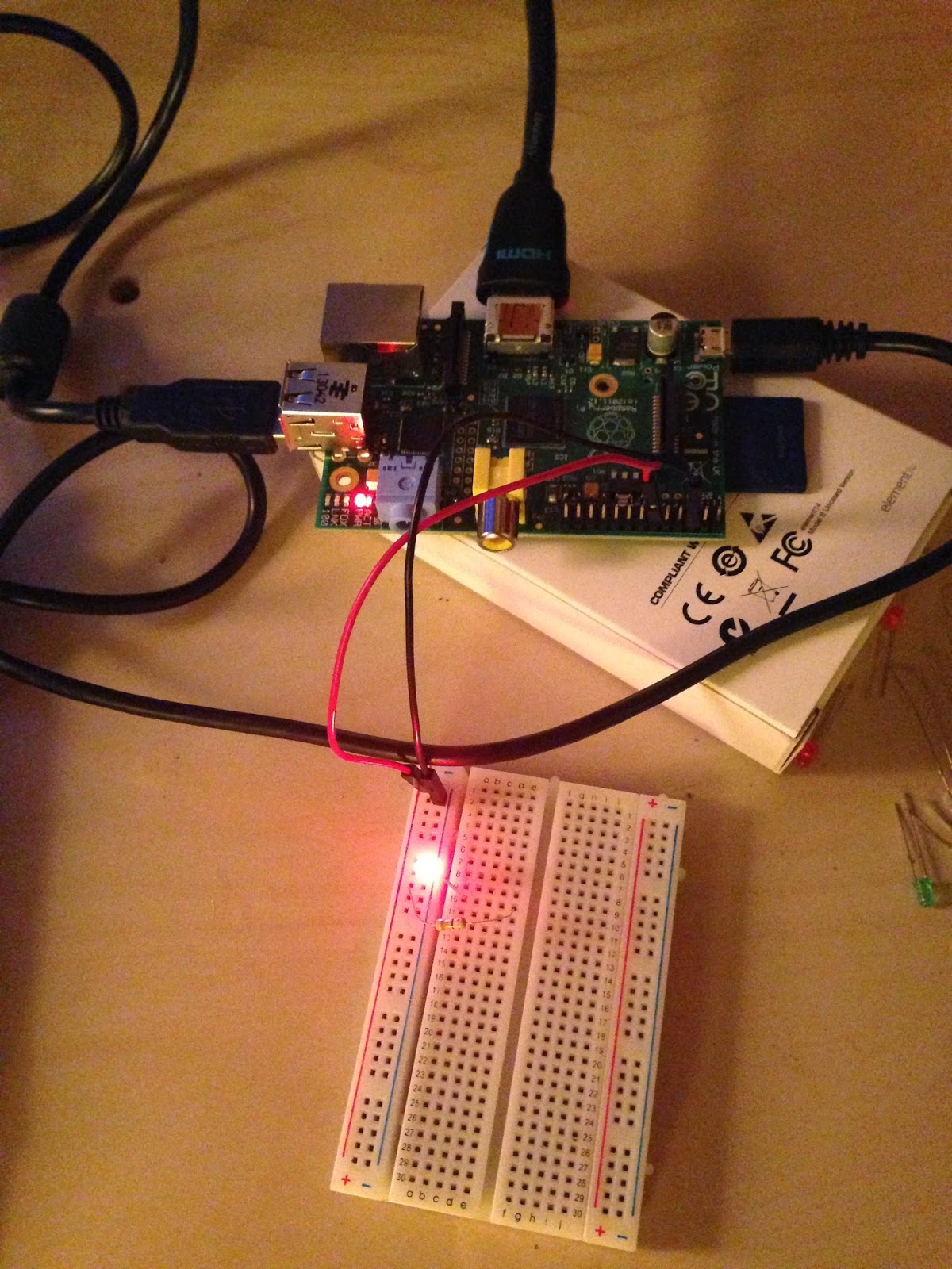
2. Wire up the breadboard!
Pick a GPIO pin. Attach the female end of one breadboard wire to the GPIO pin, and the male end to the positive slot on the breadboard. (I picked GPIO 18 b/c it is close to ground.)
Connect the other breadboard wire from ground on the RPi (third down on exterior side) to negative slot on the breadboard.
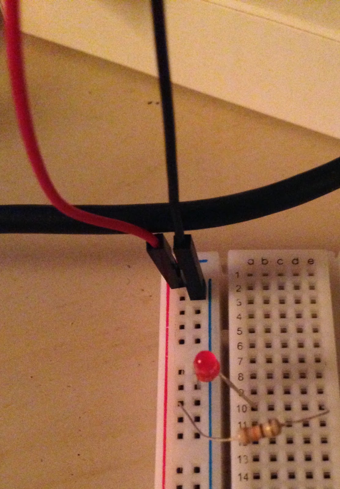
Connect the resistor from the positive series of holes to an open row on the breadboard (I picked row 10).
Connect the long side of the LED to the same row the resistor is in. Connect the short side to the negative slot.
Make sure nothing explodes (just kidding that probably won't happen :) )
3. Write a quick Python program.
The program switches the GPIO pin between on and off, turning the LED on/off as it switches. Save the program somewhere easy, like the Desktop.
Here's my code if you need some assistance:
import RPi.GPIO as gpio
import time
#SEtup pin 18 as an output
gpio.setmode(gpio.BCM)
gpio.setup(18, gpio.OUT)
#define data to be the value of pin 18
#data = GPIO.IN0(18)
#Make an LED flash on and off
while True:
gpio.output(18, gpio.HIGH)
print('Light is on.') #Optional printout of status
time.sleep(1) #changing the number increases/decreases length of signal
#print(data)
gpio.output(18, gpio.LOW)
print('Light is off.') #Optional printout of status
time.sleep(1)
#print(data)
4. Run the program!
 In the terminal window, go to the folder where you saved your program. The command cd + the directory name (ex. /home/pi/Desktop) will take you there.
Run the program by typing sudo python "ProgramTitle".py
As long as everything is connected and the program does what you think it does, the LED will flash.
That's it! Super simple, and it means that this little RPi computer just controlled a physical object wooooo!!!
Optional fun:
- Change the timing of the blink.
- Connect a couple more LEDs the same way you connected the first (these will be in parallel with each other).
- Connect additional GPIO pins to more LEDs and change the timing (remember to also add in the appropriate code).
 |
| www,atariarchives.org |
As shown in the photo to the right, breadboards usually have columns for positive and negative (red and black, respectively) that are connected electrically all the way down the board. Each row contains 5 holes that are also connected.
The resistor needs to go in between the LED and the power source to limit the amount of current, or electricity, flowing through the LED. The LED would be brighter w/out the resistor, but it will probably burn up super quick.
Happy building!


No comments:
Post a Comment