Tuesday, August 5, 2014

Portable Solar USB Charger

Portable USB chargers are incredibly useful for adventures in the great outdoors, festivals, traveling, or if you are out-and-about all day. Adding in a solar panel provides an additional source of portable power useable (nearly) everywhere. 
The whole project can be built for ~ $20, even if you don't have a soldering iron!

Parts
  • 1.5W Solar Panel 9V 
    • Suggested to use a low-power solar panel, typically if you are not using a charge controller.  
    • Note that the solar panel voltage output MUST be higher than the battery output for it to actually charge.
  • 1N914 Diode or similar diode
    • This protects the solar panel by allowing current to flow only from the panel to the batteries (aka prevents discharge from the batteries onto the solar panel).
    • If you choose a similar diode, be sure it works w/ the given solar panel specs (voltage/current output).
  • USB car charger
  • Rechargeable 9 V battery**
  • 9V Battery Case (or use alligator clips)
  • Project container (e.g. tupperwear, altoids tin, cookie tin, etc.). Be creative!

Tools
  • Wire Strippers
    • Scissors also work. To strip the wire, make cuts on both sides and pull off insulation w/ your fingers.
  • Electrical Tape
  • 5-minute epoxy, or other similar adhesive (gorilla glue probably works)
  • Soldering iron.
    • Other methods for making electrical connections: twist wires together and coat in epoxy. Other connections can be MacGyvered together; take apart old electronics for connectors and wires, use paperclips, and be creative w/ conductive objects like pennies.
  • Multimeter, if available. Massively helpful for testing electrical connections and checking if the circuit works as expected. 

Background Info
advenira.com
Solar panels are awesome for many reasons: 
1. Renewable energy technology, woo!
2. Handy in remote locations (like Burning Man..).
3. Lifetime of 25 - 30 years.
etc.*

solar-wind.co.uk

Solar panels, or photovoltaic (PV) panels, output direct current (DC). Digital devices, like cellphones or iPods, run on DC. This means our charging circuit is fairly simple. As in the photo on the left, we need a panel, a battery, and our device, or load. Charge controllers regulate current flow primarily to protect the battery. We can avoid using one in our USB charger, but they are ideal for larger systems.

The solar charging system works w/out the batteries. The batteries are there so you can use the system whenever you need it.

 
A lil' bit about USB
As shown in the photo to the right, USB chargers have 4 pins. All USB chargers output 5 Volts (V) DC on the USB Vcc pin. However, the amount of output current depends on the type of USB charger. There are three main types: a standard downstream port (500 mA), a charging downstream port (1500 mA), and a dedicated charging port (900 mA).  

Apple USB is a bit trickier (unsurprisingly..); one of the data pins is set to 2.7 VDC. So, if you finish your portable USB charger and you want to charge an iPhone or iPod, you need to increase the voltage (aka use a bigger battery.. or two 9V batteries connected together in series.


Build Process


Note: if you are using the epoxy method for connecting wires, wait until after you've tested the whole system to coat w/ epoxy..  epoxy is rather permanent and once it is set there is little you can do besides curse at it (won't really help, but might make you feel better!).


The silver band is on the right, away from the panel.
1. Strip wire on end of solar panel (remove colored insulation to expose the metal).
No leads on the panel and there's no soldering iron?! It's all good! Get creative.
Here's one way: tape two wires onto the metal pads on the back of the panel w/ electrical tape (colors don't really matter, but convention is red = positive and black = negative). Test it w/ a multimeter, or by connecting the leads to the USB car charger to make the "charging" LED light turn on. Coat in epoxy, let dry & you're done!

 2. Connect diode to positive end of solar panel lead. If possible, solder the two ends together. Otherwise, twist wires & coat in epoxy at the end. Super important: install the diode so that the side w/ the silver band is connected to the battery, like in the photo to the right.


3. Connect diode to positive (red) side of battery holder. Connect negative (black) solar panel lead to negative battery holder lead. 


4. The front metal part of the USB car charger is the positive terminal. One of the metal side tabs is the negative terminal. Determine which side of the USB car charger is the negative (or ground) side. 
Here are a couple easy ways:
-- Open up the charger; see which metal tab is connected to a wire.
-- Use the panel to turn on the charger. Connect the positive battery/solar panel lead to the front metal lead. Touch the negative battery/solar panel lead to each side. The side that causes the "on" light to light up is the negative side.


5. Connect the negative battery/solar panel lead to the negative tab on the USB car charger. Connect the positive battery/solar panel lead to the front metal lead on the USB car charger. 
There are a few ways to do this, depending on your available tools and materials. The easiest way is to use alligator clips (and coat them in epoxy when it's all done & tested).  


 6. Test it! Connect a USB device (like the Raspberry Pi!!) and make sure it lights up. 
If it works, epoxy all the electrical connections, put it into a container and take it w/ you on an adventure! 
Once your first version works, make upgrades and modifications as necessary! Google is super helpful.


*More info about solar!
Solar panels have a relatively low energy efficiency rating, typically around 12-15%. Research is continually improving solar efficiency, and a lab in Germany set the world record for solar cell efficiency at 44.7%. 

In 2012, average costs of solar per watt were between $1 - $2, with some as low as $0.70 per watt. Although this does not include the cost of additional equipment (e.g. batteries, transformer for AC applications, mounting system, etc.), it is beginning to seriously compete with fossil fuels. Yay, solar!!

**Why a 9 V battery? 
USB car chargers expect 12 VDC from the car, but will accept between 6 VDC and 14.5 VDC. Using a single 9V battery is the easiest way to get a sufficient input voltage for this USB circuit in order to get an output of 5 VDC.

Thursday, July 17, 2014

Recycled Instruments: Stringed Instruments

Music is a universal and unique medium through which humans communicate. In the modern age, there are innumerable ways to create music using diverse, non-traditional materials. Personally, I'm slightly obsessed w/ DIY and upcycling, so I took this approach and built a series of recycled instruments. 
Here are my three favorite stringed instruments!

Box Guitar

Materials: 
Cardboard box
Toothpicks/skewers
Rubber bands
& lots of hot glue


How to build:
1. The cardboard box acts as the resonance chamber. Fold the box so that there is a gap somewhere on top. Play around with different box shapes and gap sizes to find a sound you like.

2. Test the stretchiness of your rubber bands. Determine what sounds you like, and note how much they need to be stretched to make those sounds. Organize the rubber bands by pitch (high vs. low).

3. Insert a skewer or toothpick into the box where you plan on anchoring one end of the rubber band (right side in the photo above). Hot glue it into place and add a dab of glue to the top to keep the band from slipping off. 
(It's easiest to start w/ the lowest notes, since those are the longest.)

4. Stretch the rubber band across the gap. Test various sounds by stretching the rubber band at different lengths. Stop when you find a sound you like, and mark where you want the skewer (either w/ a pen or by poking a hole into the box). 
You can get two, or three, unique notes by shaping the rubber band into a triangle. This takes some trial and error and a good deal of patience, but is oh-so satisfying when you find the right notes.

5. Insert skewer(s) & glue into place, again adding a dab of glue at the top. 

6. Repeat 2 - 5 as necessary. Remember to keep testing the sounds as you go, checking the harmony of new notes w/ those already installed. 

7. Glue top flaps of box for structural support. 

8. Decorate! 

That's it! It's recommended to go slow and glue only when you're completely satisfied w/ the notes. It's possible to fix it later, but it's easier to get it right the first time :) 


 Polygonalin 


Materials:
Styrofoam/paper cup
A bundle of toothpicks/skewers
Rubber bands
Hot glue!

How to build:
1. Poke hole in center of cup

2.Stick a bunch of toothpicks around the outside of the cup. The number and spacing determine the types of sounds you get, so test out various combinations.

3. When you are satisfied and/or fed up, hot glue the toothpicks onto the cup. Add a dab of glue onto the top of the toothpick (again, to keep the rubber band from slipping off).

4. Add in rubber bands! Create and test different polygon shapes. Ideally each side will sound out a unique note.
Three rubber bands each w/ three distinct sounds gave me enough notes to enjoyably and easily create music.

TaDa! Play away! Skewers make a convenient plucking tool.


Cupsichord

Materials:
Styrofoam/paper cup
Cardboard
Toothpicks/Skewers
Rubber bands
Hot glue

How to build:
1. Glue a circular piece of cardboard to the bottom of the cup (structural support).

2. Poke a hole through the middle of both the cardboard and cup.

3. Stick and glue three or more toothpicks onto the cup.

4. Stick and glue a skewer into the cardboard horizontally; the setup is similar to a banjo or guitar or any other stringed instrument w/ a neck.

5. Glue toothpicks onto the end of the horizontal skewer. Check the spacing by stretching a rubber band to those lengths to be sure you are getting the sounds you want.
(These allow for more combinations of notes on one lil' cup instrument!)

6. Attach rubber bands and make music!


As always, please let me know if you have any questions! And post your creations! I love seeing the awesome ideas other people concoct :D

Wednesday, July 9, 2014

Blinking Light(s) w/ the Raspberry Pi!

Getting a light to blink using the Pi's GPIO pins is the equivalent of a "Hello World" test program. If that doesn't make sense, all you need to know is that this project is a sweet first project that covers a lot of the basics that will help when you design and build your own ideas!


1. First, gather the following materials:
Breadboard (or wires/alligator clips)
2 Breadboard wires (Male-to-female are ideal)
1 (or more!) LED (Light Emitting Diode)
1 330 Ohm resistor
And the rest of the normal stuff to set up the RPi (SD card, power cord, keyboard + mouse (or just keyboard), HDMI cable and monitor.)

2. Wire up the breadboard!
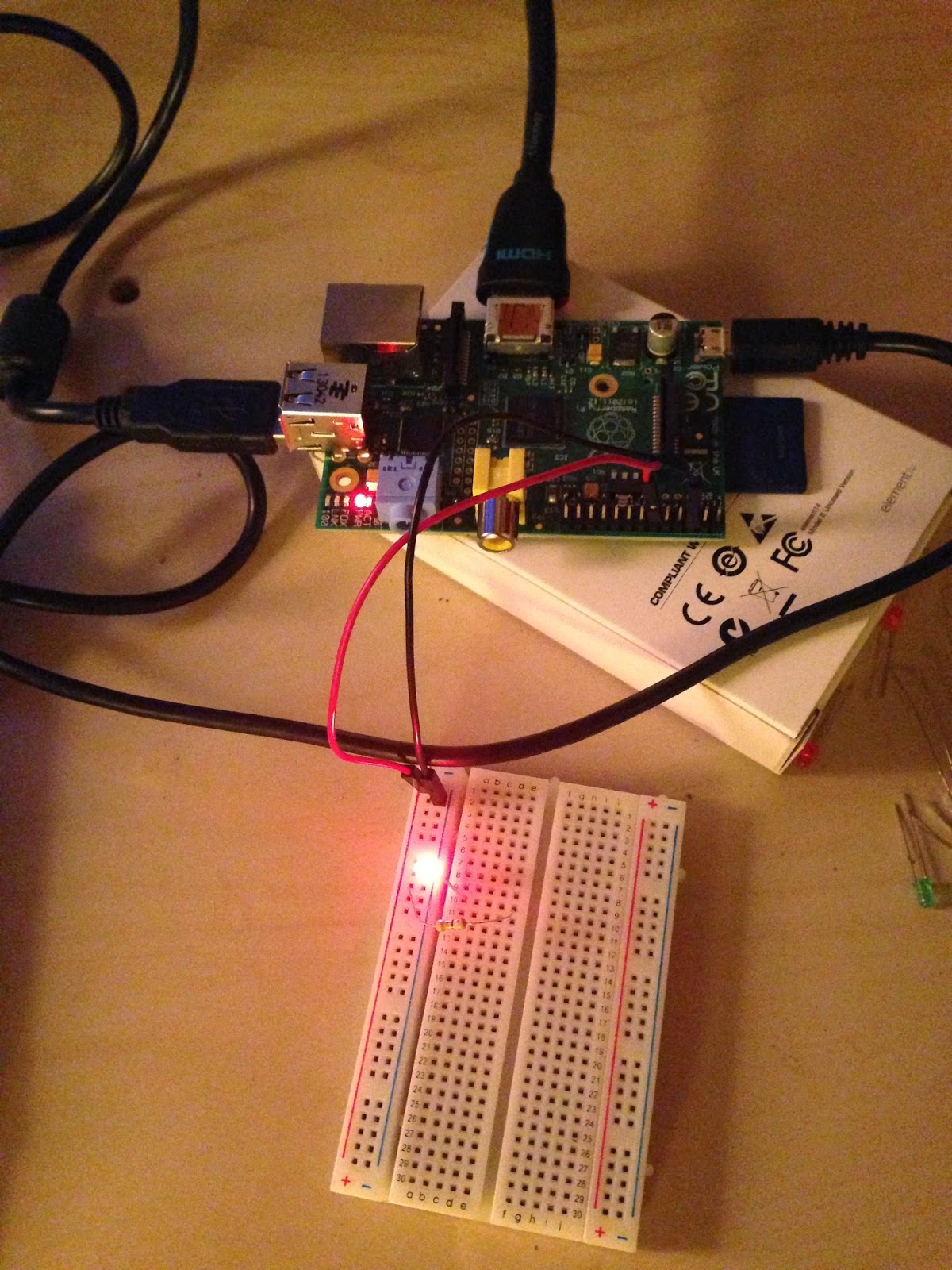
Pick a GPIO pin. Attach the female end of one breadboard wire to the GPIO pin, and the male end to the positive slot on the breadboard. (I picked GPIO 18 b/c it is close to ground.)
Connect the other breadboard wire from ground on the RPi (third down on exterior side) to negative slot on the breadboard.
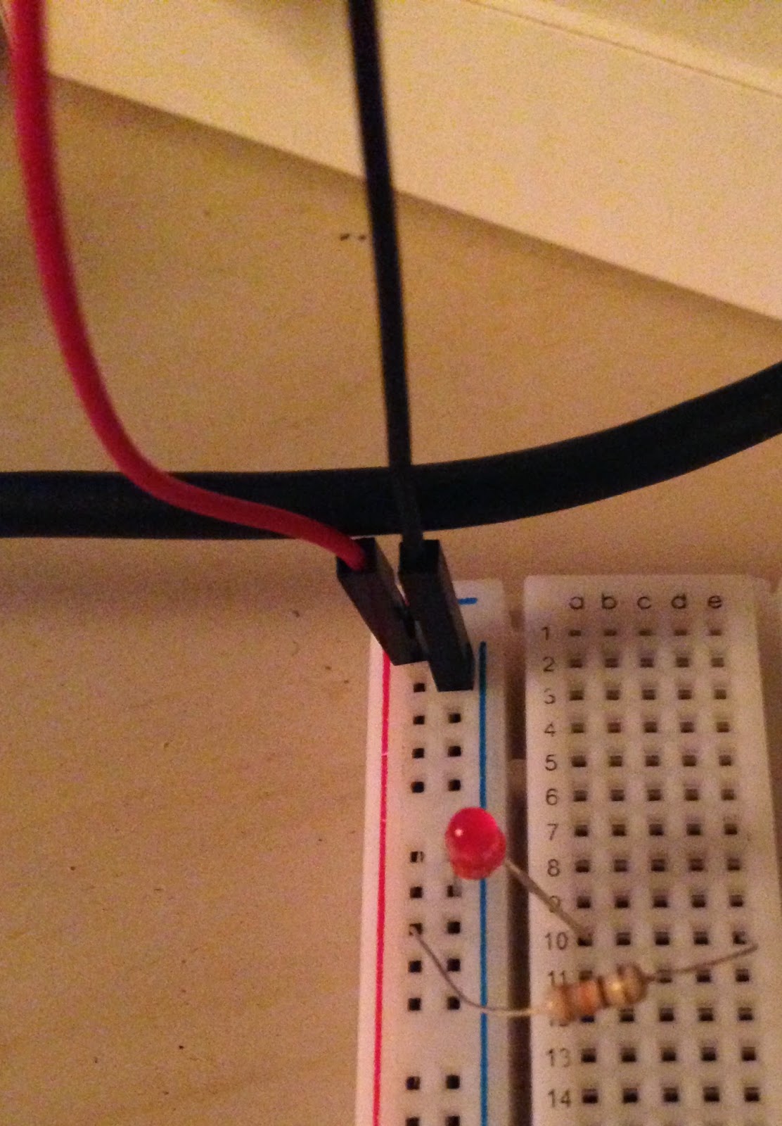
Connect the resistor from the positive series of holes to an open row on the breadboard (I picked row 10).
Connect the long side of the LED to the same row the resistor is in. Connect the short side to the negative slot.
Make sure nothing explodes (just kidding that probably won't happen :) )

3. Write a quick Python program.
The program switches the GPIO pin between on and off, turning the LED on/off as it switches. Save the program somewhere easy, like the Desktop.

Here's my code if you need some assistance:
import RPi.GPIO as gpio
import time

#SEtup pin 18 as an output
gpio.setmode(gpio.BCM)
gpio.setup(18, gpio.OUT)

#define data to be the value of pin 18
#data = GPIO.IN0(18)

#Make an LED flash on and off
while True:
    gpio.output(18, gpio.HIGH)
    print('Light is on.') #Optional printout of status
    time.sleep(1) #changing the number increases/decreases length of signal
    #print(data)
    gpio.output(18, gpio.LOW)
    print('Light is off.') #Optional printout of status
    time.sleep(1)
    #print(data)

4. Run the program!

In the terminal window, go to the folder where you saved your program. The command cd + the directory name (ex. /home/pi/Desktop) will take you there.
Run the program by typing sudo python "ProgramTitle".py
As long as everything is connected and the program does what you think it does, the LED will flash.
That's it! Super simple, and it means that this little RPi computer just controlled a physical object wooooo!!!


Optional fun:
- Change the timing of the blink.
- Connect a couple more LEDs the same way you connected the first (these will be in parallel with each other).
- Connect additional GPIO pins to more LEDs and change the timing (remember to also add in the appropriate code).


www,atariarchives.org
Helpful info:
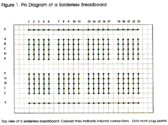
As shown in the photo to the right, breadboards usually have columns for positive and negative (red and black, respectively) that are connected electrically all the way down the board.  Each row contains 5 holes that are also connected.

The resistor needs to go in between the LED and the power source to limit the amount of current, or electricity, flowing through the LED. The LED would be brighter w/out the resistor, but it will probably burn up super quick.


Happy building!


Thursday, June 12, 2014

Setting up a Raspberry Pi to Control Physical Objects, Pt. 2

Source: http://www.aoakley.com

What cool things can you do with the Raspberry Pi?

Well, you can use it like a normal computer: word processing, surfing the internet, streaming videos, etc. You can write programs on it using the Idle software (Python language), Scratch, or Linux. This might seem mundane, but keep in mind that you bought this lil' computer for $40 freaking dollars (+shipping and handling). If you have kids, this is a seriously fantastic option for a first computer, especially because you won't mind as much when they spill apple juice all over it (or if you're like me and still spill apple juice on computers, this is a great option for a backup computer..).


GPIO Pins!
By far the coolest way to use the Pi is to interface w/ the real world using the GPIO pins (that row of 26 pins adjacent to the RCA video port, or the yellow port). The GPIO pins have different functions as shown in the photo below: 17 of the 26 total pins are actual GPIO pins, while the rest are either ground, a power source (5 VDC or 3.3 VDC) or labeled "DNC" for "Do Not Connect"/"N/C" for "Not Connected" (connecting to these pins may short the Pi, so it is recommended to avoid these).


You can print this GPIO Leaf and stick in on the board!


GPIO pins can be used as an input or an output. As an input, the pin can distinguish between two values: HIGH*  and LOW. As an output, you can send an ON, or HIGH signal (3.3 VDC), or an OFF, or LOW signal (0 VDC). These pins can be used for tons of physical tasks, like turning on/off lights (Christmas light choreography, anyone??), controlling motors, reading sensors, and honestly pretty much anything you can conceive, as long as you build a proper circuit.

Some of the GPIO pins also have more specific functions, such as SDA (data line), SCL (clock), etc.; if you're reading this as a beginner don't worry about these just yet. When you find a project you're excited about you'll naturally learn these functions as necessary. 
*High input threshold is a signal of ~ 1.8 VDC, although it can vary between 0.8 - 2.0 VDC. This means that any signal coming in to your GPIO pin that is above 0.8 VDC may be read as "HIGH" by the RPi. 

Advanced users will be happy to know that you can modify many of the GPIO characteristics from software (this link also has the robust GPIO electrical specifications).

For absolute beginners, here are some helpful things to know about the GPIO pins:

GPIO pins operate on Direct Current (DC) voltage. Unless you want to see smoke come out of the RPi, do NOT input Alternating Current (AC) signals, like the one that comes out of the wall. 

Be very careful about what you connect to the GPIO pins. You will not be able to control a motor directly from a GPIO pin; in this instance, the GPIO pin functions as a switch, rather than the actual power for the motor. Here's a great tutorial on how to control a small motor.


Looking for more inspiration? Here's a general list of 25 cool things to do w/ your RPi! You can also Google "Raspberry Pi projects" or browse the Instructables website for RPi projects.

The next post will cover a simple circuit you can build and control w/ the Pi.

Sunday, June 8, 2014

Setting up a Raspberry Pi to Control Physical Objects, Pt. 1

There are a slew of relatively simple systems to control physical objects w/ software. The most popular options are Arduino, the Raspberry Pi, and BeagleBoard. I'm an avid Raspberry Pi advocate, so let's start with that! 

The RPi is a simple & inexpensive computer that has general purpose input and output (GPIO) pins that interface w/ the real world. 

((This tutorial assumes you are a beginner, but some technical jargon is included. Please feel free to comment if a term or phrase is not clear.)) 


What is a Raspberry Pi?
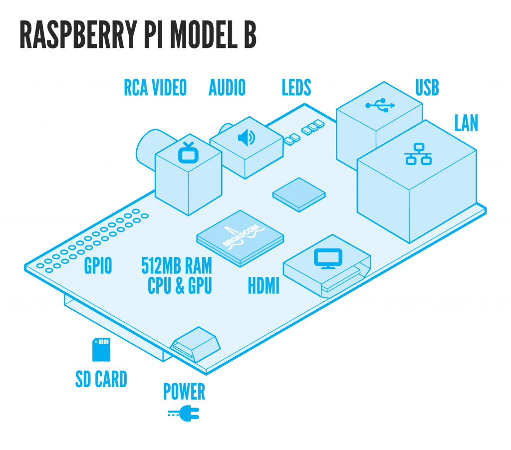
The Raspberry Pi is a credit-cared sized computer created by the Raspberry Pi Foundation, an educational charity based in the UK. It is designed to promote programming, computing, and interfacing with the physical world. It can control pretty much anything you are capable of conceiving.

There are two versions of the Pi:
-- Model A is cheaper w/ fewer features; 256 MB of RAM, one USB port and no Ethernet port.
-- Model B is more expensive, but has 512 MB of RAM, two USB ports, and a 100mb Ethernet port.

Where to purchase:
You can buy a Raspberry Pi from a variety of distributors. Model B from Adafruit is $40 (+ shipping & handling). 


Other supplies:
The Pi is literally just a computer. You'll need a few additional supplies to set it up and use it (unless you're a wizard). Think of it like a puzzle: collect the remaining pieces to customize an inexpensive interactive computer! To make the process easier, here's a list of parts w/ explanations (you probably already have some):


1. Power Cord
The Pi runs on a micro-USB power supply, similar to many phone chargers. More specifically, the Pi needs 5 VDC and at least 700 mA. The Pi Foundation recommends a power supply that can provide 1200 mA. You can get one for less than $10, best values ~ $5, if you're crafty you can find cheaper (or free). Here's a google search for some that meet the best specs. Take note of where the power cord plugs into: wall socket, USB, etc.

2. SD Card
The Pi needs an SD card for physical memory storage (it doesn't have a built-in harddrive or solid state drive). For ~ $6, you can buy an SD card with a pre-installed operating system and necessary software from the Pi Foundation's Swag store here. 
With slightly more effort, you can buy any generic SD card and download the software here. This is fairly easy with a Mac system; if you chose to go down this route, here's a great tutorial.

3. Monitor & Display cable: HDMI/DVI cable or RCA composite video lead.
Most modern monitors and TVs have HDMI ports for video (you can connect your RPi to your TV, woo!!). If you don't already have one lying around, HDMI cables are found at RadioShack, Best Buy, Amazon, Ebay, etc. You can also get a HDMI converter cable for monitors or TVs w/ different ports. Older monitors are easy to find for free; many places of business, colleges/universities, and friends are happy to part with old monitors, or you can check out e-waste recycling bins.

4.USB Keyboard & mouse (easiest way to set up).
Any keyboard and mouse w/ a USB connection will work w/ the Pi.

Optional Supplies: 
5. Ethernet Cable  (easiest way to connect to the Internet for Model B). 
Usually blue and lying around in some pile of cords you know are important. You can also buy them at places like Radio Shack, Best Buy, Amazon, etc.
Source: http://www.bitrebels.com

6. USB WiFi chip.
Getting a USB WiFi "dongle" (yes, that is actually what it is called..) will allow you to connect to the Internet w/out an Ethernet cable. This requires some fairly involved setup, but it is completely doable for a RPi user of any experience level. Here are two methods: 
--Using wicd-curses,
--Using GUI application

7. Audio Lead (if not using HDMI)
To get sound w/out an HDMI cable, you'll need a standard 3.5mm jack to connect to speakers or headphones.

8. Case
The Raspberry Pi is designed to be a bare-bones computer to reduce cost as much as possible. However, cases are helpful protection from inevitable accidents and improve the mechanical connection of cables. There are TONS of awesome cases made specifically for the Raspberry Pi, although feel free to get creative and make your own!


Basic Setup:
Source: http://rayhightower.com
1. Insert SD card. Plug the RPi into a monitor & connect the keyboard and mouse via USB. An Ethernet cord is also recommended as it makes installing software on the RPi much easier .

2. Plug the power cord into the RPi. Make sure you see a light turn on. (Yes, I honestly needed to include this step because this is an all too frequent problem for me.) 
Always do this after everything else is plugged in.

3. If everything has been connected properly, you will see a start-up window. Every operating system (OS) will be different, but initial setup is simple and manageable. 
If you have a pre-loaded RPi-specific OS, or you have Raspbian or Adafruit's OS, here's a super straightforward tutorial on how to fully configure the RPi. 
Changing a few basic settings will definitely make life easier. From personal experience, if you have an SD card larger than 2 MB it's useful to initially expand root partition to use the full SD capacity. If you want to avoid a command line window, you can specify Desktop launch whenever you power up the RPi.
The default username is "pi" and the password is "raspberry". 
Note: Since every OS is different, if your Pi doesn't launch into the startup window, if you are still on the terminal window type "startx" into the command line. If that doesn't work, leave a comment and we can troubleshoot together!  

4. Essentially that's it! Once you're at the desktop, you can use the Pi much like any other computer! Some basic programs: Midori is a simple Internet browser, Leafpad is a word processing program, Idle is a Python programming environment, and Scratch is kid-friendly programming language.

I will add more on how to set up the wireless, or other topics as requested. 
Creative Commons License
This work by Jennifer Fox is licensed under a Creative Commons Attribution-NonCommercial-ShareAlike 4.0 International License